01AL₂O₃
Caustic cracking
Alumina refining
Welds and heat-affected zones exposed to concentrated caustic liquor, elevated temperature and residual fabrication stress.
 Request an inspection
Specialist ultrasonic inspection · Australia-wide
Australia-wide specialist inspection for early-stage cracking in welds and pressure equipment—before a fine, branching flaw becomes an integrity event.
Detect · Characterise · Size · Report
Available Australia-wide · Call 1300 004 647
01 / Failure mechanism
SCC develops when a susceptible material, tensile stress and a specific corrosive environment intersect. The component can look sound while a crack network grows beneath the surface.
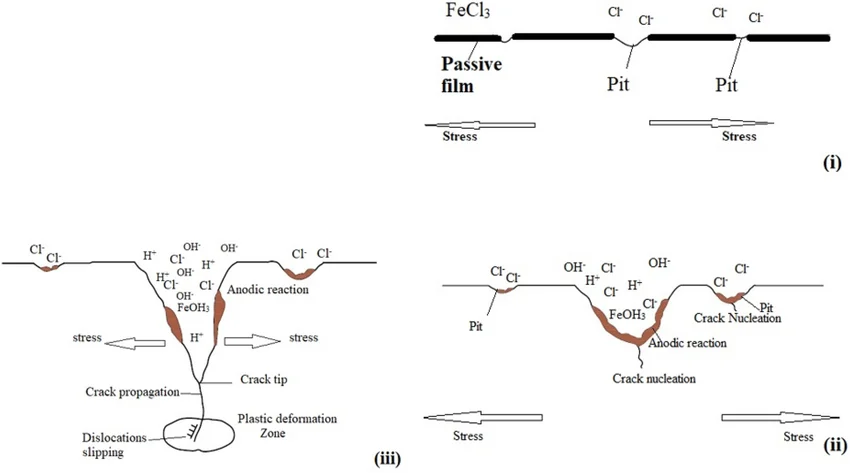
Uniform wall loss is usually visible or measurable with a thickness survey. SCC is localised, crack-like and mechanism-dependent. Fine branches can initiate at pits, weld toes or heat-affected zones and propagate with little obvious surface evidence.
02 / Industry-specific risk
There is no generic “SCC scan.” Inspection is scoped around the alloy, chemistry, temperature, fabrication history and stress state of the asset.
Caustic cracking
Welds and heat-affected zones exposed to concentrated caustic liquor, elevated temperature and residual fabrication stress.
Ammonia SCC
Carbon-steel storage vessels, spheres and process welds where oxygen, water and tensile stress can drive cracking.
Chloride SCC
Austenitic stainless piping, vessels and insulated equipment exposed to chlorides and temperature.
Amine SCC
Carbon-steel absorber, regenerator and piping welds subject to local hard zones and residual stress.
Carbonate SCC
FCC gas plants, syngas and sour-water systems where carbonate chemistry and tensile stress intersect.
Environmental cracking
Welds and pressure equipment requiring a mechanism-specific plan for wet-H₂S damage and crack-like indications.
03 / Inspection strategy
We combine complementary ultrasonic datasets where geometry and access allow, then report what was covered, what was found and what the indication means.
Multiple beam angles interrogate the weld volume and likely crack planes from a controlled scan position.
Full matrix data can be reconstructed with selected wave modes to improve imaging around difficult crack morphology.
Diffracted signals from crack tips can support depth measurement when the flaw, geometry and access suit the technique.
Method selection is procedure-led. Final techniques, coverage and acceptance criteria are confirmed against the asset, material, geometry and applicable inspection requirements.
04 / Evidence chain
The output is built for the asset engineer: traceable locations, retained datasets, indication characterisation and clear next actions.
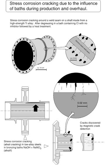
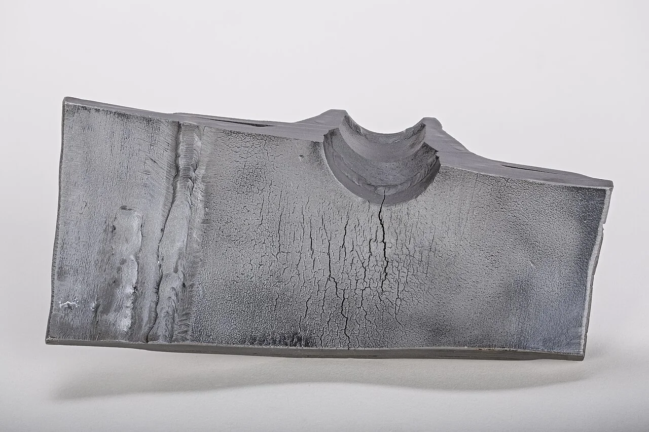
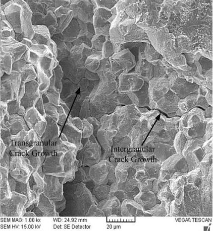
Crack morphology and position inform the ultrasonic examination plan.
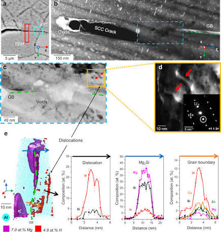
05 / Documented cases
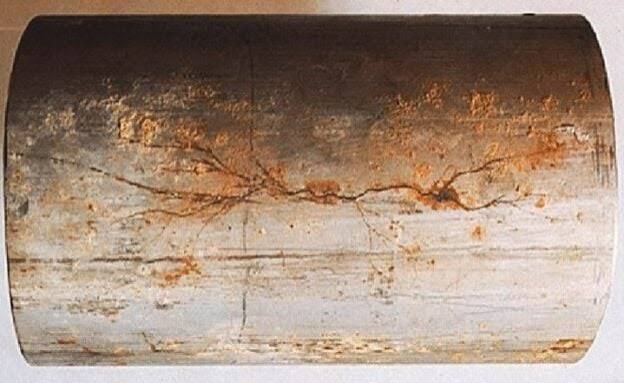
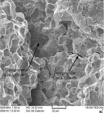
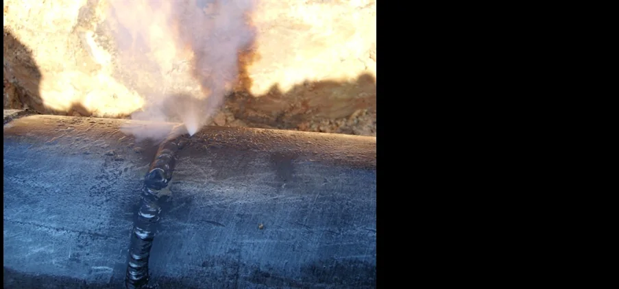
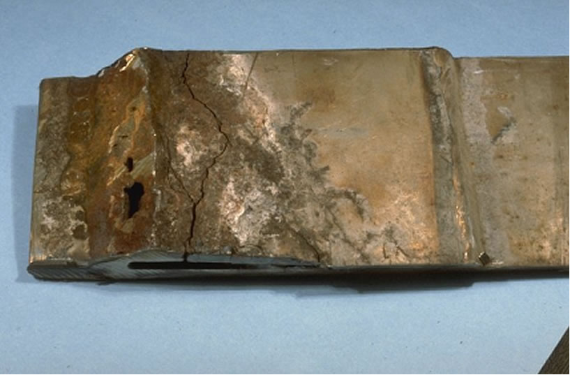
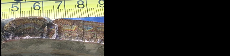
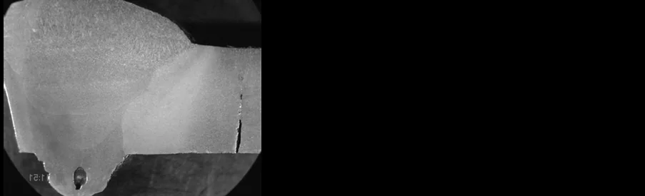
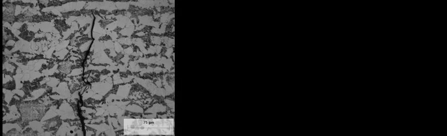
Real failure evidence is more useful than generic industrial photography. These examples connect the visible component, weld location, fracture surface and microscopic crack path.

06 / Project sequence
Confirm asset, material, chemistry, temperature, fabrication and operating history.
Select access, probe configuration, calibration blocks and coverage strategy.
Scan controlled locations and retain interpretable datasets for review.
Correlate responses, crack orientation, morphology and through-wall extent.
Deliver traceable findings and practical recommendations for engineering review.
Technical basis
Project procedures and reporting can be scoped with reference to the relevant asset code and examination standard, including:
Applicable editions, acceptance criteria and personnel requirements are confirmed during project scoping.
Australia-wide inspection support
Share the asset, material, service environment and timing. We’ll review the likely mechanism and come back with the next practical step.